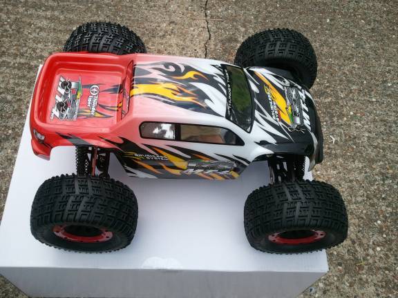
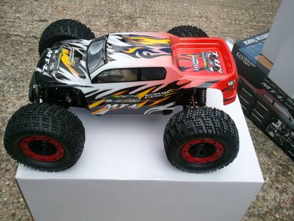
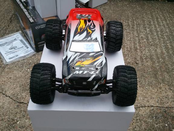
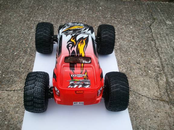
Thunder Tiger G3 MT4
Electric Brushless LiPo 4WD Monster Truck
On this page you will find a full history of this excellent monster truck including documentation, photos, videos and repairs.04/08/2012 Bought from Just Kits Hessle Road. Hull. I finally bought something from a decent local model shop. I should have bought some of my earlier toys here. I had used the shop previously for odds and ends and had always received good, friendly, correct advice.
This year I thought I would go for a brushless electric LiPo car.
Here is an account of its unboxing, specifications, buying and preparation, and diary.
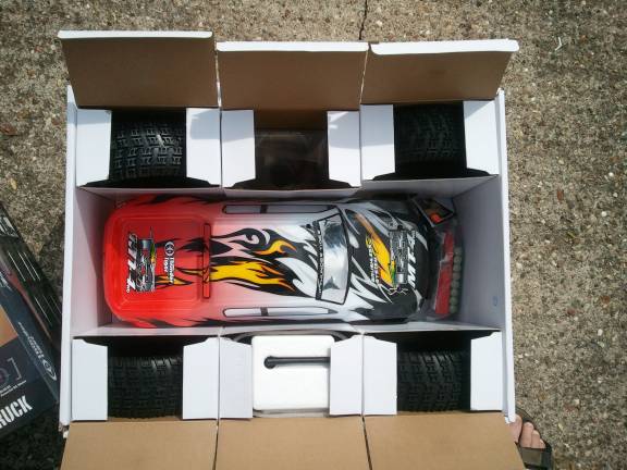
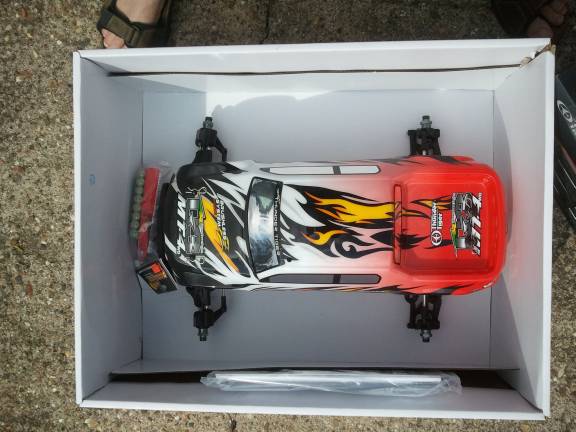
Unboxing
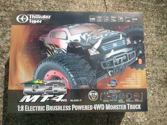
Specifications
The information presented here has been gathered together from many sources, mainly from the manuals I received with the vehicle. I have tried my best to verify everything here is correct, but I cannot guarantee that it is.Vehicle
Wheelbase 360mmWeight 4180g
Length 532mm
Width 434mm
Height 240mm
Compatible with most ST-1 series parts
Heavy Duty Steel Diff Ring/Pinion
Adjustable Steel Turnbuckles
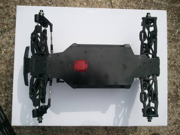
Compact Molded Chassis Brace And Cover
New Concept Monster Truck Body
CNC Machined Aluminium Motor Mount
CNC Machined Steel Pinion Gear
Equipped Front/Rear/Center CVD Drive Shafts
ACE RC Brushless Power System for 1:8 Scale Car
Center Drive Shaft Guard For Cable Protection
High Current Super Deans Plugs
Anodised Aluminium Oil-Filled Shocks
17mm Aluminium Wheel Hubs
Rear, Center and Front Fluid Filled Differentials
S2008MG Metal Gear High Torque Servo For Steering
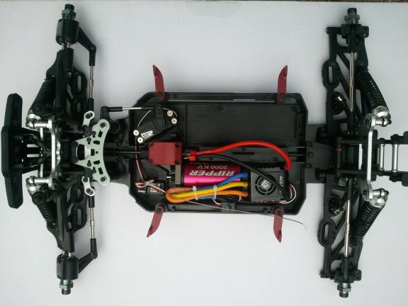
ACE RC BLC-150C race spec ESC and super torque 2000KV motor combo
Transmission
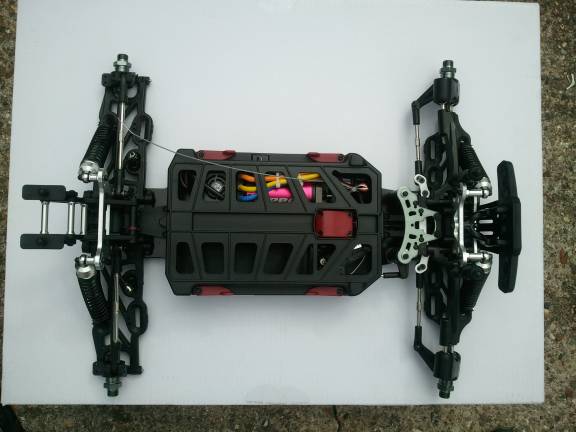
Hardened steel differential rings. All the diffs contain a full set of steel diff gears and diff fluid inside in combination with full set of bearings throughout the drive train.Suspension
Composite nylon suspension arms. The shock bodies are made of anodised Aluminiumwith quick adjustment clips. The shock towers are made from 4mm thick Aluminium plate with multiple shock mounting positions and the whole chassis is strongly stiffened with a compact molded chassis brace and cover. You can also fine tune for the optimal camber and toe setting with adjustable turnbuckles and suspension blocks.
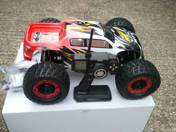
Box Contents
Pre-Assembled Chassis, wheels requiring assemblyPre-Printed Hi-Flow Dynamic Body
ACE RC 1:8 Car Brushless Power System
Cougar 2.4GHz 3-CH LCD Transmitter and micro receiver
8kg/cm Metal Gear Steering Servo
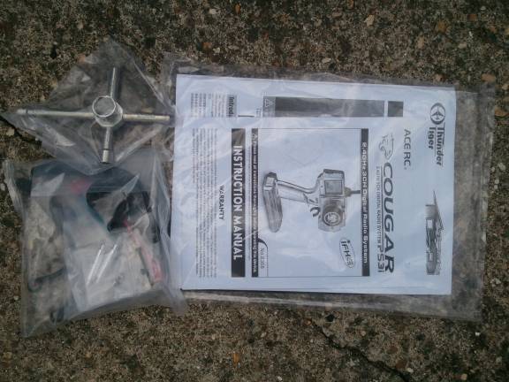
L Hex Wrench Set
Cross Wrench for Changing Wheels
Documentation
Suspension and steering additional fittings
Required For Operation, Not Supplied
AA- Batteries x8 for transmitter2S- 1P Lipo with deans plugs 1 or 2 packs
3S-4S 1P Lipo with deans plugs 1 pack only (this mention of 1 S3 pack is confusing as later all the documentation states a total of 6S is maximum, so 2x3S is acceptable)
Motor
Ace Ripper IBL40/20 brushlessFeatures:
Designed for 1/8 scale buggy and truggy applications
High temperature copper wiring
Aluminium case, red in colour
Three Leads with 3.5mm Male Bullet Connectors, three 3.5mm Female Bullet Connectors and Instructions
Requires:
Compatible ESC such as the Ace RC BLC-80C ACEM8080, or the BLC-150C ACEM8081 4-6S LiPo battery (do not use LiPo batteries with more than six cells)
Specs:
IBL 40/20
kV: 2000
Outer Diameter: 40mm
Length Without Shaft: 74mm
Shaft Diameter: 5mm
Shaft Length: 18.5mm
Weight: 385g
Rm: 0.005 ohm
Max Volts: 23 V
Io @ 10V: 2.3 A @ 10 V
Continuous: 1350 W
Continuous Current: 75A
Peak Current: 150A
Sensorless
Electronic Speed Controller
BLC-150C ESCCompatible with all sensorless brushless motors and most of sensored brushless motors such as Novak, LRP and Feigao, etc.
Excellent start-up, acceleration and linearity features 3 running modes (Forward only with brake, Forward/Reverse with brake, Forward/Reverse immediately)
4 steps of maximum reverse force adjustment.
Proportional ABS brake function with 4 steps of maximum brake force adjustment, 8 steps of drag-brake force adjustment and 4 steps of initial brake force adjustment.
9 start modes (Also called 'Punch') from 'very soft (Level 1)' to 'very aggressive (Level 9)'.
Multiple protection features: Low voltage cut-off protection / Over-heat protection / Throttle signal loss protection / Motor blocked protection.
8 steps of timing adjustment by software.
Built-in switch mode BEC has a powerful output to supply all the electronic equipment.
Easily programmable with only one button and compatible with pocket-sized Program Card.
Firmware can be updated through a USB adapter (Optional equipment).
Splashproof and dustproof.
Stable and reliable.
Output: Continuous current 150A, burst current 950A.
Input: 6-18 cells NiMH/NiCd (3300mAh or higher) or 2-6 cells LiPo.
BEC Output: 5.75V/3A (Switch mode built-in BEC).
Resistance: 0.0002 Ohm.
Motor Supported: Sensorless brushless motors
Suitable Car: 1/8 Buggy / Truggy / Monster.
Size: 58mm(L) 46.5mm(W) 35mm(H).
Weight: 105g (Without wires)
Suitable Brushless Motor:
When working with 4 cells Lipo: >= 4.5T (KV<=3000)
When working with 6 cells Lipo: >= 6.0T (KV<=2400)
The above T number is based on the value of a 4074 sized motor(Diameter=40mm, Length=74mm)
*******
KV is number of times motor spins per volt per minute.
The 'T' stands for turns. This is the number of times the wire is wrapped around the motor stator. A smaller number of turns typically equals less resistance, and more power. A higher number typically means more resistance, and less power. The factors are complicated, but that's it in a nutshell.
However, as yet I have been unable to find out what the 'T' value of the Ripper IBL 40/20 is.
*******
Suitable Car: 1/8 Buggy / Truggy / Monster Truck.
Size: 58mm(L) * 46.5mm(W) * 35mm(H).
Weight: 105g (Without wires)
Radio Control
Features:Configured for operating surface R/C models
10-model memory slots
AUX channel
IBDC-Interactive Bi-Direction Communication
FHSS-Frequency hopping spread spectrum
SIBL-Security ID binding link
FSPC-Failsafe programmable individual channel
Easy to read LCD display Screen
Electronic digital trims
Sub-trims
ARC
Servo reversing
EPA
Dual Rate
Voltage Indicator
Adjustable wheel tension
Low voltage alarm
Folding antenna
Includes:
Ace PS3I 2.4 GHz transmitter
TRS401SS 2.4GHz 4channel Receiver
Instruction manual
Requires:
AA Cells: Eight for transmitter
Servos depending on type of vehicle
Receiver battery (or BEC Battery Elimination Circuit)
Specs:
Transmitter:
Power Supply: 8 AA alkaline, NiCd or NiMH cells
Size: 220x99x182mm
Weight: 443g
Current drain: 130mA@9.6V
Receiver:
Receiving Frequency: 2.4GHz
Power Requirement: 4.8 - 6V
Size: 35.6 x 14.2 x 18.3mm
Weight: 6.5g
Diary
04/08 2012: Buying There were a few cars that were in my budget range/specification to choose between but this one seemed the sturdiest which seemed a good point to me. One hiccough just as I was about to commit to it was discovering that the truck does not come with batteries. The cost of the two S2 5000MaH LiPo batteries took it well out of my range. However, a 3900 S3 would do the job, the shop owner brought it down to only a smallish amount over my budget and so off back home I happily trotted with a large box under my arm.Setting up consisted of the usual checking of screws nuts and bolts and reading of manuals which I promised the shop owner would be done before switching on. Charge up the LiPo and bolt on the wheels with a bit of added thread locker. Only comment about the excellent main manual with parts listing and diagrams is that it seems to get confused between the front end of the car and the rear end, labelling those sections the wrong way.
ESC: Checking the Electronic Speed Control (ESC) was the most brain taxing part. It is possible to buy a 'card' that is temporarily placed between the receiver and ESC so you can make the various settings without having to press a button, listen to and count beeps whilst watching red or green LEDs flashing specific numbers of times whilst pressing buttons at the right time to get all the settings in correctly. As it happens, initially, all the settings I wanted were the factory default ones but I never trust that the settings are actually at default and did a reset to make sure. Next came setting up the throttle neutral, maximum and minimum points on the ESC and checking the failsafe.
Radio Transmitter:
Binding: Firstly the transmitter has to be bound to the receiver. Switch on the transmitter whilst holding the red 'Binding SW' button on the back of the transmitter. Release the 'Binding SW' button and the green LED next to the button starts to flash. Press and hold the 'Bind' button on the receiver whilst switching on the receiver. The LED on the receiver will flash green/red. Release the 'Bind' button on the receiver and the LED will change from flashing quickly to a steady green to indicate the process is complete. Binding may take from 3 to 10 seconds. If binding fails, the LED on the receiver turns red. If this happens, switch everything off and start the process again.
Setting up the failsafe: After binding the transmitter and receiver, set up the failsafe. Turn on the transmitter and then the receiver. Hold the 'Bind' button on the receiver for 10 seconds. The receiver LED will flash green. Do not let go of the receiver 'Bind' button. Set steering and throttle to the failsafe position (steering neutral, throttle neutral for electric car). Release the 'Bind' button on the receiver. The LED turns red then green to indicate success. Test the failsafe by putting the steering to full lock and switching off the transmitter, the steering should return to straight. Throttle failsafe can be tested by first removing the pinion.
Transmitter Functions: Up, down, left and right keys are to the right of the steering wheel. Throttle trim is to the left of the steering wheel. Steering trim is above the steering wheel. Dual Rate trim is below the steering wheel. The Auxilliary button is below the Dual Rate trim button and has no function here. On the left side of the transmitter is a 3 position power switch. Off, Display and On. On is for normal use. Display allows you to change settings within the transmitter without actually transmitting anything.
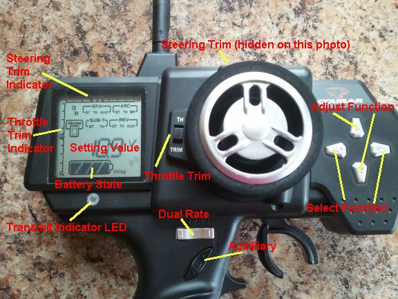
Beep can be toggled on/off by switching the transmitter on whilst holding the up and right buttons, the only indication of this function's setting is whether you hear a beep on button press or not. Be sure to let go of the keys quickly after power up as it is possible to unintentionally change other settings.
Select settings by pressing the right and left buttons until the desired setting is highlighted in the LCD screen. The currently selected setting is indicated by a square around it. The setting's current value is displayed above the battery state indicator. Adjust the highlighted setting by pressing the up and down keys.
D/R (Dual Rate):
Range 0% to 150%. Default 100%. A higher setting increases steering sensitivity. Be aware that adjusting it above 100% is likely to put strain on the steering servo if the steering is turned to its full travel point.
EPA (End Point Adjustment):
ST (Steering). Range Right and Left 0% to 120%. Default 100%. Turning the steering left or right will select left or right for adjustment. Current selected adjustment shows as an 'L' or a 'R' in the LCD.
TH (Throttle). Range H (High) 0% to 140% and L (Low) 0% to 160%. Default both to 100%. Pulling the trigger back selects 'H' in the LCD and pushing the trigger forwards displays 'L' in the LCD.
AUX (Auxiliary). No effect on this model so I will not describe it.
ARC (Adjust Rate Control):
This adjusts the response curve of steering, throttle and brake.
ST (Steering). Range -100% to 100%. Default 0%. Adjusts both left and right simultaneously. This setting adjusts steering responsiveness close to the neutral point. 0% is a straight line from straight to full lock. A lower value provides less responsiveness near the neutral point. A higher value increases responsiveness near the neutral point. This setting does not change the end point of the steering.
TH (Throttle). Range -100% to 100%. Default 0%. Adjusts throttle responsiveness setting a curve from neutral to full. 0% is a straight line from lowest to highest. A negative value dips the curve, giving a broader power band, less acceleration nearer the neutral point. A positive value elevates the curve giving more acceleration with less trigger movement.
BR (Brake). Range -100% to 100%. Default 0%. Adjusts brake responsiveness curve. 0% is a straight line from none to full. Negative dips the curve for milder braking power. Positive elevates the curve for sharper braking power.
Model Number:
Range 0 to 9. Default 0. 10 model settings can be stored in the transmitter memory.
SUB-T Sub Trim:
ST (Steering). Range L125 to R125. Default R0.
TH (Throttle). Range L125 to H125. Default H0.
Sub Trim allows very minor adjustments to throttle and steering trim.
REV Reverse:
Range NOR or REV. Default NOR. Changes the servo direction. Throttle, Steering and Auxilliary can be altered separately.
First Run
Ready to go, a steady first run. After about 30 seconds the car stopped with the red LED on the ESC flashing. Low voltage cutout. It mentions this in the ESC manual which insists that the low voltage cutout should be set manually. It transpires that the three cell LiPo that I got confuses the ESC, it thinks it's a four cell one and so as soon as the voltage drops a bit, the low voltage cutout operates. Circumvented by setting low voltage cutout to 'None' (No cutout according to the manual). Pressing buttons and counting flashes was a bit of a grim job, losing count, getting confused and changing settings I didn't intend to change wasn't fun. Several resets later, I finally got it all worked out and set up as intended.That worked, also I discovered after using it for 20 minutes, the ESC cuts out anyway at 3.20 volts. A little confusing but maybe it will all become clear at a later date. Added later, it does. See entry 24/08/2012.
A few steady runs around the garden. No disasters, no real problems. Lots of fun.
One minor problem. There is a fan on top of the ESC to which the only access for cleaning is had by dismantling the whole circuit board from the unit, breaking the seal between the heat sink and the motherboard and prizing it out so you can then remove debris that will inevitably be sucked in there. On a nitro or petrol engine carb, a bit of oily gauze or foam might reduce power a bit but at least it stops grit getting in. On a hot circuit board I assume any reduction of airflow into the fan is not at all a good idea. On the first run, there were several pieces of dried grass in the mechanism which I sucked out with the vacuum cleaner as blowing and cocktail sticks with sticky tape didn't cut the mustard.
06/08/2012 Several runs in the garden and up the street getting used to it. A few wheelies and a flip. Really great fun. Looking forward to building some ramps and taking it to a field to give it a proper test. Notice that there is a disturbing front wheel wobble when reversing for any length of time or at speed causing loss of control if allowed to continue. It would seem this is to be expected. The right hand rear axle is rubbing slightly on the lower part of the shock absorber. Doesn't look to be much of a problem but I will keep an eye on it.
07/08/2012Using some of the other LiPos that I have I have now had quite a few runs with it. Slalom course and ramp in the garden. No problems to report. Runs well. Ready for a try in a field.
08/08/2012 09/08/2012 A lot more runs, spectacular wheelies and speeds down the street. Couple of hard knocks but absolutely no sign of damage or wear and tear although a few battle scars evident on the underside.
10/08/2012
23/08/2012 Used a lot since my last report. No damage other than a few more scars on the underside caused by going up and down concrete edges. Still runs well.
The ESC is cutting out at 3.80 volts on my 3S batteries. The low voltage cutout is cutting in too soon. It is because the ESC is confused by the 3 cell pack. When you switch on, the ESC beeps the number of times for the cells it thinks are connected to it. It beeps four times when a 3S is connected, obviously wrong. Therefore it thinks there should be 16.8v in the pack when there are in fact only 12.6v. Theoretically then, the cutout should be operating at above 12v for the 14.8v pack which is only just above the starting voltage of the 3S 12.6. Hence the problem. I have tried setting the cutout to none in the ESC but it obviously hasn't done that at it still cuts out. Rather than try to do it using the switch on holding buttons, listening to beeps and counting LED flashes of different colours which quite frankly confuses me, I have ordered the program card that goes between the battery and ESC, supposedly making programming considerably easier.
The manual states that you can use the 8082 BLC ESC Program Card. I found a page on the internet that showed a further two alternatives, one of which is a rebranded version of the 8082. The Hobbywing PC2C seems to be exactly the same thing but is a lot cheaper and easier to get hold of. I have ordered one off eBay. Just under a tenner, supposedly coming from the UK. We shall see!
So, I thought I would try a 6S in the G3MT4 to see what it was really capable of. I have two exactly the same 3S 2200mah 25/35 lipos that I use in my Mini Titan. Reading it up on the internet I noticed that many people connect two LiPo batteries to make a series saddle pack using a simple connector. I had already exchanged the bullet connectors of the Mini Titan setup for Deans as these seemed much better plugs to me. This made all the batteries interchangeable. I made up a saddle connector using Deans plugs:
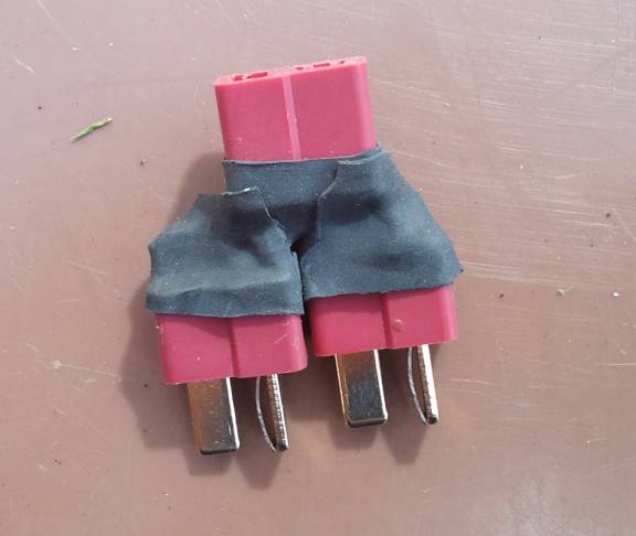
This did the job, I connected both 2200mah batteries together and tried the car out. Firstly, on power up, the ESC beeped 6 times. A good sign. The car was amazing, it really did shift now having 25.2v in it. Wheelies all over the place. I really am going to have to go to a large open area with it (video when I get chance). Then came the thought that if the batteries are being used together, maybe they should be charged together too. That would make charging a bit quicker too. So, how does the balance lead come into this? More Googling and I discovered that you can get a lead to join the two 3S balance leads together to plug into the 6S slot of the charger. Couple of quid off eBay.
I had an inkling that I had missed something though and when dealing with LiPos that is not a good place to be. As I needed a couple of things, one of which was another 3900 3S so I could double up my existing one, I hopped on the CB750CE and nipped over to Just Kits. Asking their advice, the manager wasn't quite sure, so rather than guess, he rang the MD of Overlander Batteries and asked his advice. The definitive answer was: It is OK to link two Lipos as long as they are both exactly the same capacity and size etc and (the crucial bit for me) they are both used from new together. Crucial because the 2200mah batteries I had experimented with were bought a week apart and had been used separately. Lucky escape there then.
Mr Just Kits rubs his hands as I order two new batteries from him. There goes this month's pocket money all in one go. Buy the balance lead adapter off eBay.
So, shortly, I should have one cobbled together 6S pack and 3x3S packs, giving four sets of LiPos. Plenty of running time for a field trip. With swapping from 6S to 3S all the time, the ESC will need reprogramming for the low voltage cutout between battery swaps too, pleased I ordered the programming card.
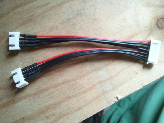
24/08/2012 Well, the eBay sellers didn't hang about. Today I received the balance lead adapter and Hobbywing programming card. I also collected the two Lipos from Just Kits. Sadly it's chucking it down with rain with a horrible forecast so it looks like there will be no testing out today, or maybe even over the long weekend. Fingers crossed.
Balance Lead Adapter
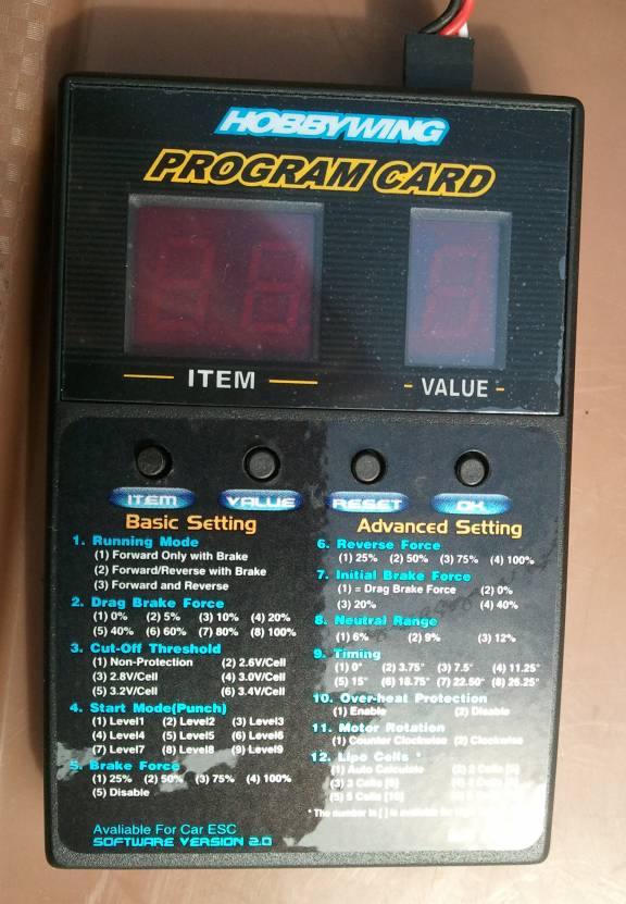
Trying out the above pictured programming card helped me understand a few things that had confused me.
You will notice that there are two columns in the settings list on the card: Basic and Advanced. I was a bit disappointed to discover that it is not possible to change the settings in the Advanced column, either using the card or the SET button on the car. These Advanced settings are also listed in the ESC manual. Either I have missed it somewhere, or it does not make it clear that the Advanced settings are for a different model of ESC to the one I have. When pressing the 'Item' button on the programming card, it cycles from 1 to 5 and then back to one again. The same using the SET button on the car, it cycles from 1 to 5 and back to 1 (there is another story, see later!). This is not really a big problem as some of those settings are changed in the transmitter, some I wouldn't want to change, but the cell selection would be handy. Now I see where the problem lies, the ESC appears to be hardwired to Auto Calculate but cannot recognise a 3S Lipo. Ideally, I should never have been sold a 3S with the car, but it's not a big problem now I think I know what was going on.
When using the card, I discovered that the Cut-Off Threshold was set to 2 (2.6v a cell) and not 1 (No Cut-Out) as I had attempted to set it to. This explains why the ESC was still cutting out. It seems that fortunately this was probably the best setting for it as setting it to 1 (No cutout) with no other way of monitoring the voltage does not appear to be particularly intelligent. Here are my calculations:
The ESC thinks there is a 4S LiPo connected when there is in fact a 3S LiPo connected so at 2.6v x 4 = 10.4v total voltage, the ESC cuts out. However, it is in fact a 3S and the 10.4v cut out is therefore actually about 3.46v per cell. So it was cutting out before it needed to by about .46v per cell. To make a 3S cut out at 3v per cell (when the ESC thinks it's dealing with a 4S), there would need to be a setting of 2.25v per cell, but there isn't. The manual says that there is a programming card that allows you to set user defined voltages but I really don't have the will to try to look for one, especially as I have only just bought this one.
For a 6S, that's simple, Option 3, setting 4. Which is 3v per cell.
So when in use, I am going to have to change between 3-2 (or 3-1 and monitor the voltage) for the 3S and 3-4 for the 6S. Pleased I got the card then.
That's the low voltage cutout sorted (hopefully).
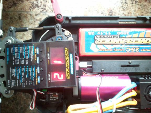
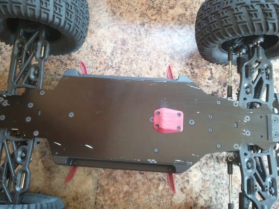
Right, now I had the settings sussed and easily changed, I thought I would once and for all get to grips with actually programming the ESC using the SET button. Removing the pinion from the motor (you can just see it not there in the above photo), I set about fiddling with the settings. The big problem I had was understanding what the manual was telling me. It was all there but wouldn't sink in. One thing confused me though, which as it turns out was the key to the whole thing. The SET button performs two tasks, throttle calibration and ESC setup, I understood this. What I couldn't get was how to separate the two. In the end I realised that to program the ESC you need to hold the SET button for quite a long time whilst switching on. This was not clearly stated anywhere. You need to wait while the red LED flashes about 18 times, the green LED then starts flashing, you then keep waiting until the green LED flashes the number of times that represent the setting you want to change.
I had not been waiting long enough, letting go of the SET button too soon and as a result had been setting the throttle range calibration instead which is by the way:
One green flash, control to neutral, press SET.
Two green flashes, control to maximum and press SET.
Three green flashes, control to minimum and press SET.
The ESC then resets and is ready to use.
I had been inadvertently setting, maximum and minimum to the same place, at neutral! DOH!
To factory reset. Normal power on then hold SET for 3 seconds. Then set the throttle range calibration.
Current settings for ESC, experimenting with punch and braking:
3S: 2 1 2 1 2
6S: 2 1 4 1 2
Managed an hour in the garden before the rain came. Going well.
26/08/2012 The twin batteries lasted 92 minutes today, the cutout operated well before the selected 3v low setting though (about 3.4v). There must be something I am missing there.
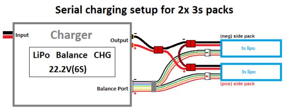
Something else I missed. Why do I alway find out these things the hard way? In short (pun intended), the balance lead adapter MUST be connected to the series connected Lipos in the correct way.
Initially I did not understand this. The first time I connected the batteries to the charger, by chance, they were connected the correct way, but the second time, as I plugged in the second battery balace lead to the Y adapter there was a bit of a flash. The adapter lost a bit of peg but fortunately everything else was OK. On Googling around I found various bits of info, one of which for instance said you should connect the lead to the batteries before connecting it to the balance port on the charger (not sure that was the answer). Another, in adverts, states that you must know what you are doing before using the lead but does not mention what I am about to mention here. I did come across a few mentions of having to connect the leads the right way but could not understand that it would make any difference as they will only plug in one way.
Eventually, it clicked though, the batteries when joined in series must be seen as one battery with a single positive side and a single negative side (OK, I know, rather obvious). Therefore, as the balance leads have a positive and negative side, they must also be connected the right way around. The diagram below is the best way to show the correct way of connecting the balance leads. This saves many words of possibly misleading description:
So, sent off for a new adapter lead. I will colour code it when it arrives to save future errors.
28/08/2012 Went to the playing field at Paull with all my cars and Peter with his. Had a mixed do with various problems with the other cars but the MT4 went really well. Interesting to see the front wheels when in the air appear to increase in size as the tyres change shape with centrifugal force. Great wheelies, no photos or video unfortunately. No damage. Batteries lasted about 20 minutes when going flat out constantly. Huge turning circle at great speed, doesn't really have a lot of grip on grass. Great fun.
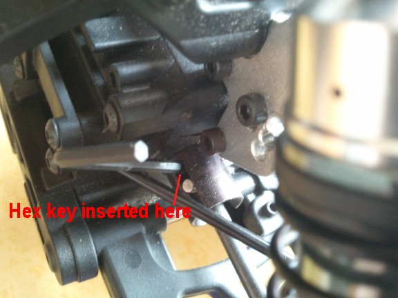
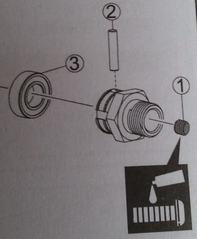
On cleaning and checking, no problems found except a future problem discovered. The wheel design is such that removal is going to be difficult. The nut on the inside of the wheel (Hex drive PD8924) will turn easily in the plastic recess of the wheel. The threadlock I have used does not free the thread when moved and therefore requires the nut to be held whilst the outer wheel mounting nut is fully unscrewed. That is not possible as it is hidden in the recess on the inside of the wheel. I found two solutions to this.
The first solution is to stop the hex drive turning by placing a rod, in this case a 2.5mm hex key, into the gap of the Differential Outdrive to stop the drive turning and therefore holding the inside nut. I know this is a bit dodgy as there are a few pins and things that could get damaged doing this, but holding the wheel as well spreads the pressure and seems to work without damaging anything (including the hex key!):
One way to remove the wheels
The second solution I discovered later by examining the diagram in the manual. There is a pin held by a grub screw that holds the hex drive in place. Remove the grub screw from the center of the hex drive (accessible deep in the outside, center of the wheel). The pin can then be worked out of the hex drive, it is located on the inside of the wheel, you can just see its ends if you rotate the wheel slowly. It should just drop out with a bit of movement of the wheel. It can be re-inserted by balancing it all together with the pin in place with the vehicle on its side. With the wheel removed in this manner, there will rarely be a need to actually undo the nut that holds it onto the hex drive.
Hex drive, pin and grub screw
31/08/2012 Paull with the lads and all our cars. Even my 4 year old grandson had a carefully monitored go ( I had the throttle ).
MT4 went well, until an ominous rattling started coming from it on hard acceleration. No more wheelies. On inspection later discover a loose grub screw on the main rear drive shaft where it connects to the rear diff. Tightened it up after putting a dot of threadlock on it. That fixed it. There is a lesson, despite all my checks, that was one I missed, it had no threadlock on it from new. I was very lucky not to lose the grub screw and get some damage somewhere. Also, the screw from the steering servo horn went missing but the horn stayed in place, replaced screw from my vast collection of crap collected over the years. John ( fingered by post mortem examination of video ) lost the aerial tube for me. Found a suitable one in the loft.
Not a bad toll considering the hammering it took. Gave the car a total strip down, examining all the diffs, screws, nuts and bolts. Saw a hint on a website about tightening up the steering servo saver to keep the nut from wedging onto the chassis and tightening up/locking the steering. On checking mine, I discovered that it was indeed wedged onto the chassis quite firmly, after winding it away from the chassis, the steering improved drastically. Will keep an eye on that in future. Examining early photos, that nut was wedged there from new. Quick test in garden shows it's ready for another blast. Turning circle improved drastically. Can't wait!
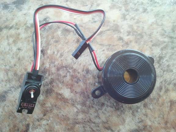
Project.An old servo with the gears and motor removed from it. Wires soldered to where the motor was and hey presto something to plug into the auxilliary channel. The peg of the potentiometer protrudes through the hole where the servo horn attached, this can be turned to fine tune things, or can be glued in place. Set the auxilliary channel end points on the transmitter appropriately. Here it's fitted with a loud 5v beeper but could be a relay to a car horn or rocket launcher. Comment added 20 10 2023: Nothing came of this :-)
24 06 2021 Unbelievable how much time has passed since I bought these toys. This car still as good as new and the child in the above video is now a young man
20 10 2023 To fund the Elco this truck is now up for sale. Contact me through my main website enquiry form if you are interested